TCP/IP Model Explained: TCP/IP Layers and OSI Model Mapping (Beginner-Friendly Guide
A beginner-friendly explanation of the TCP/IP model, the four TCP/IP layers, how it maps to the OSI model, and how encapsulation appears in packet captures.
Drake Nguyen
Founder · System Architect
Introduction: what you’ll learn in this TCP/IP model explained guide
If you’re learning networking fundamentals, this TCP/IP model explained guide walks you through the four TCP/IP layers that make the internet work, how the internet protocol suite maps to the OSI model, and how to recognize protocols in real packet captures. You’ll also see protocol examples per layer, a layer mapping table, and a step-by-step view of encapsulation in TCP/IP using beginner-friendly explanations.
TCP/IP model explained: Overview and quick history
The TCP/IP model (often called the internet model or internet protocol suite) is a practical framework for how data moves across interconnected networks. It groups related functions into four layers to make routing, addressing, and end-to-end communication easier to implement and troubleshoot than purely theoretical models.
- Purpose: interoperability between different networks and systems
- Design approach: pragmatic layering that reflects real-world protocols (IP, TCP, UDP, and common application protocols)
- Why it matters: it’s the foundation for diagnosing issues from cabling and Wi‑Fi to DNS and web traffic
How TCP/IP maps to the OSI model (layer mapping table
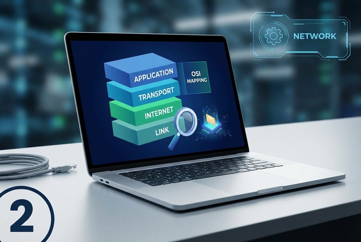
Understanding TCP/IP vs OSI model mapping helps you translate textbooks and vendor documentation into what you’ll actually see in logs, firewall rules, and packet captures. The OSI model has seven layers; TCP/IP combines some of them into four.
TCP/IP Layer             | OSI Layer(s) (approx.)                  | What it does (examples)
-------------------------+------------------------------------------+---------------------------------------------
Application              | Application / Presentation / Session     | HTTP, DNS, SMTP, FTP, DHCP, SSH
Transport                | Transport                                | TCP, UDP (ports, reliability, flow control)
Internet                 | Network                                  | IP, ICMP (routing, addressing, forwarding)
Link (Network Access)    | Data Link / Physical                     | Ethernet, Wi‑Fi, ARP (framing, MAC, media)
Use this layer mapping table to quickly locate where a problem likely lives: Wi‑Fi association is usually Link, routing failures are Internet, and timeouts can be Transport or Application depending on symptoms.
Layer-by-layer breakdown of the TCP/IP layers (with protocol examples per layer
This section answers “what are the TCP/IP layers?” and ties each one to real protocols and troubleshooting signals you can observe. It also shows where each layer fits in how TCP/IP works end to end.
Link layer: local delivery, switching basics, and framing
The link layer moves data within the local network segment. It deals with frames, MAC addressing, and access to the physical medium (Ethernet or Wi‑Fi). Many “routing vs switching” confusions start here: switching is primarily Link-layer forwarding inside a LAN, while routing (Internet layer) forwards between networks.
- Common protocols/tech: Ethernet (802.3), Wi‑Fi (802.11), ARP
- Key concepts: framing, MAC addresses, MTU, VLANs (environment-dependent)
- Quick checks: link status, interface errors, switch MAC table, Wi‑Fi signal/association
Internet layer: IP, routing, and IP addressing basics
The internet layer is where IP lives (IPv4/IPv6). It provides logical addressing and routing so packets can move between networks. If you’re studying IP addressing and subnetting basics, default gateways, and route selection, you’re working at this layer.
- Common protocols: IPv4, IPv6, ICMP
- Key functions: addressing, forwarding, TTL/hop limits, path/MTU considerations
- Quick checks: IP/mask/gateway, routing table, ping/traceroute behavior
Transport layer: TCP vs UDP, ports, and reliability
The transport layer provides process-to-process communication using port numbers. TCP is connection-oriented and reliable (sequencing, retransmission, flow/congestion control). UDP is connectionless and lightweight, often used where low overhead or low latency matters.
- Common protocols: TCP, UDP
- Key concepts: ports, sessions, three-way handshake (TCP), loss handling
- Examples: HTTPS over TCP; DNS often over UDP (and sometimes TCP)
Application layer: user-facing services (HTTP, DNS, SMTP, DHCP
The application layer is where services and applications communicate using protocols such as HTTP(S), DNS, SMTP, SSH, and DHCP. When people say “the website is down,” the issue might be here—or it might be lower, and the application symptoms are just the first visible sign.
- Common protocols: HTTP/HTTPS, DNS, SMTP, FTP, SSH, DHCP
- Common tools: curl, dig/nslookup, application logs
- Typical failure modes: name resolution errors, authentication failures, misconfigured endpoints
Encapsulation in TCP/IP and packet flow (step-by-step example
Encapsulation in TCP/IP means each layer wraps data with its own header so the next system can interpret and forward it. Here’s a simple request flow when a client loads a web page over HTTPS:
- Application: the browser prepares an HTTP request (carried inside TLS for HTTPS).
- Transport: TCP creates segments and uses source/destination ports (e.g., ephemeral port → 443).
- Internet: IP adds source/destination IP addresses for routing across networks.
- Link: Ethernet/Wi‑Fi frames carry the packet on the local medium using MAC addresses.
Link:      Ethernet Frame [dst MAC | src MAC | EtherType | ...]
Internet:    IP Packet     [src IP | dst IP | protocol | ...]
Transport:     TCP Segment [src port | dst port | seq/ack | ...]
Application:     Data      [TLS + HTTP payload ...]
On receipt, the destination host decapsulates in reverse order (Link → Internet → Transport → Application) to deliver data to the correct process.
Practical examples and tools: Wireshark, tcpdump, and reading a sample packet
To make the model concrete, capture traffic and identify which headers belong to which layer. Wireshark offers rich decoding; tcpdump is lightweight and great for servers.
Example: capture HTTP/HTTPS traffic on Linux (adjust the interface name as needed):
sudo tcpdump -i eth0 -nn -s 0 'tcp port 80 or tcp port 443' -w capture.pcap
In Wireshark, open capture.pcap and inspect:
- Link: source/destination MAC, ARP requests, VLAN tags (if present)
- Internet: source/destination IP, hop limit/TTL, fragmentation indicators
- Transport: TCP flags (SYN/ACK/FIN/RST), retransmissions, UDP queries
- Application: decoded HTTP, DNS queries/responses, SMTP sessions
Common troubleshooting tips (layer-by-layer
A fast way to troubleshoot is to move through layers with targeted tests. The symptom often shows up at the Application layer, but the root cause can be Link, Internet, or Transport.
- Link layer: verify link up/down, Wi‑Fi association, switch port/VLAN, interface errors/drops.
- Internet layer: confirm IP address, subnet mask, default gateway, and routes; use ping/traceroute for reachability.
- Transport layer: test ports (e.g.,
nc -vz host 443), review firewall/NAT rules and state tables. - Application layer: validate DNS and DHCP behavior (
dig, logs), confirm service health and certificates for HTTPS.
Conclusion: TCP/IP model explained (summary and next steps
This TCP/IP model explained guide showed how the four-layer internet model works, how TCP/IP maps to the OSI model, and how encapsulation helps you interpret real traffic in tools like tcpdump and Wireshark. Next, practice by capturing a short browsing session, identifying the Link/Internet/Transport/Application headers, and tracing one failed connection to the exact layer where it breaks.